Introduction
Today’s post is a little weird, and I’m sure doesn’t fit the rest of my content… but oh well, here we go! Yay, hubs!
As you may know, I love retro hardware and networking, so what better than to combine both?
Well earlier today, I came across a decommissioned hub at work and thought I’d give it a new home. One where it’ll probably end up running for another decade…
While I’m fairly familiar with hubs, already running a few in my retro lab, this switch caught my eye as somewhat interesting.
Reading through the documentation, it looks to be a standard run-of-the-mill hub…
“So why are you writing an article on it?”
Well I’m getting there now. As a habitual tinkerer and generally curious person, I decided it wouldn’t do any harm if I took the case off… taking me down the usual rabbit-hole of finding something strange.
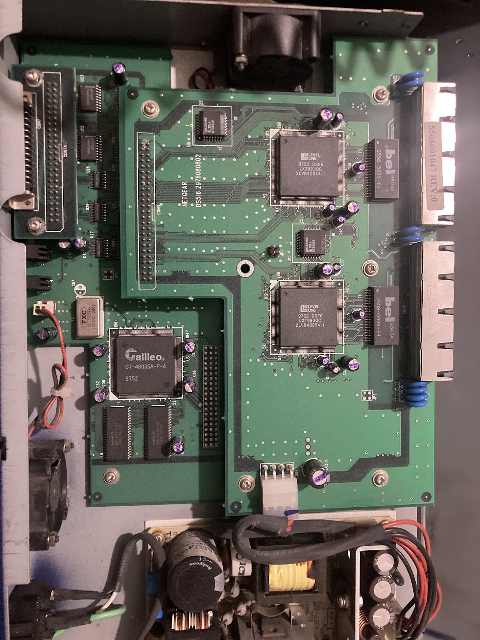
Inside you may notice a few large, square, chips with the labels “Galileo” and “Level One”. I’ve seen similar chips in the past, but mainly inside switches… foreshadowing?
Well it turns out that Galileo chip is actually a switch chip. From a little further research, I found that the chip only actually supports 2 ports. A little weird for a device, that for one is a hub and not a switch, but also has 16 ports… I’ll come back to this in a bit.
Now, I’m not really that much of a PCB or circuit guy, I much prefer zapping myself with wires instead of green boards but I do understand the very basics. Using this knowledge, I can fairly easily come up with an educated guess on what things do.
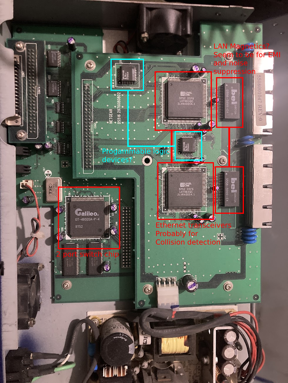
As you will see in the image below, there is 1 set of components per 8 ports, of which I assume interconnect with the switch chip? Of course, this is only a guess and I’ll probably spend a few hours mapping the circuit out later.
In cyan, you can see 2 chips, these from a rough search online (and not much came up) seem to be programmable logic chips, of which I assume do the job of switching packets between ports within the block? Or they may handle the logic for whether W packet in X port group is intended for Y device in Z port group. I’m not entirely sure of there purpose as of current, it’s just a guess.
The 2 larger chips are Ethernet transceivers. From a lengthy search, I’ve come to the conclusion these are likely for the hub’s collision detection system. This is pretty essential in the “faster” hubs, since they are broadcasting every packet sent out to every port, and more speed means more collisions.
Highlighted on the far right are what seem to be known as “LAN Magnetics”. From what I can find online, they seem to just be there to filter out EMI and electronic noise and aren’t necessarily there for any “modern” purposes. They don’t seem to be in any of my older hubs, so it’s possibly just something new to me.
Thank you for reaching the end!
Enjoyed reading this post? Feel free to read more!
Leave a Reply